Geevor Tin Mine Gallery 3

Geevor Tin Mine Gallery 3: More images of the buildings around the site. The wooden buildings sharp and angular make unusual and attractive photographic patterns.Once again Bob Orchard has supplied much of the information.

For someone with a camera the whole site is a great place to take detailed images.
geevor tin mine gallery 3
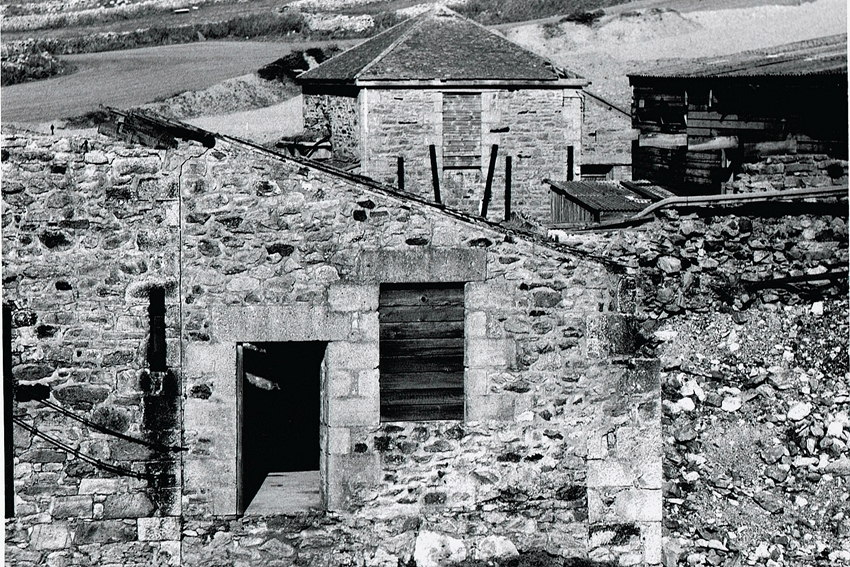
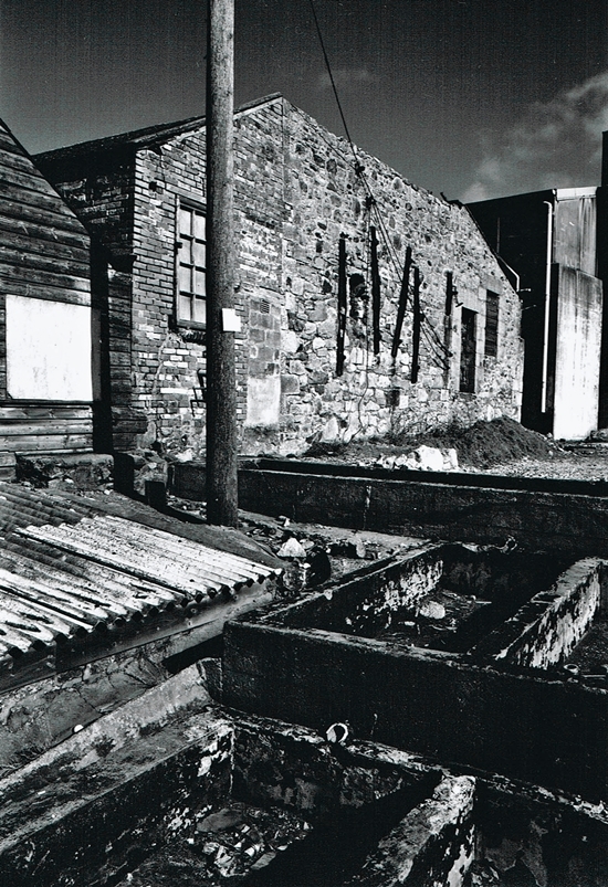
Geevor Tin Mine Gallery 3.1 – An external view of one the Bruton Calciners at Geevor.
These were used to roast the tin ore which contained quantities of Arsenic. This was also recovered and sold as a valuable by product. The furnace was of a circular arrangement which rotated so the ore was burnt in an even pattern. These were in use upto the 1930’s when the improvements in the recovery process made them redundant.
The series of shallow concrete pits in the images were used to extract metallic copper from water rich in copper. This was the process of “cementation”, or quite simply depositing copper onto scrap iron. Just as a matter of interest, the worm & worm wheel that drove the vertical shaft that rotated the revolving hearth is still under the Calciner.
geevor tin mine gallery 3
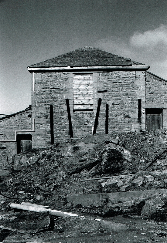
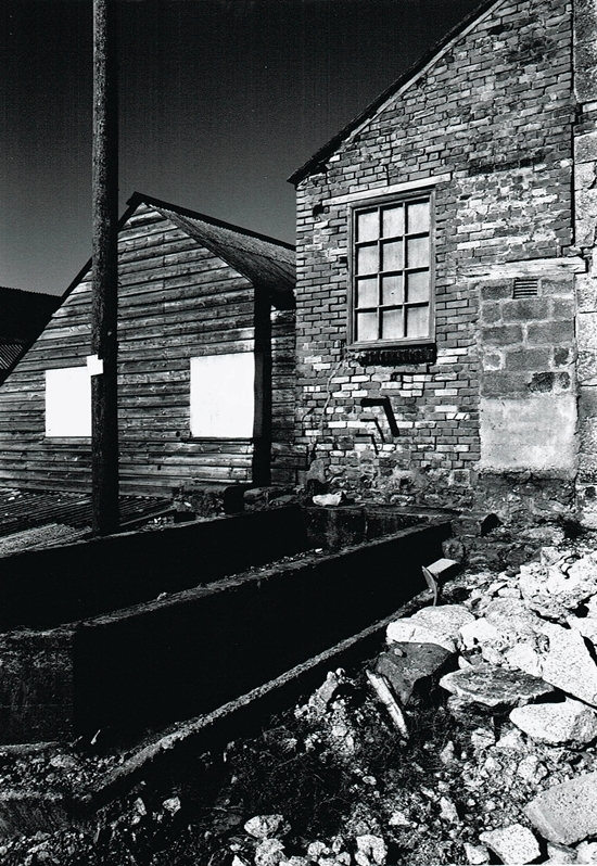
Geevor Tin Mine Gallery 3.2 – A second image of the Calciner and the adjoining building.

geevor tin mine gallery 3
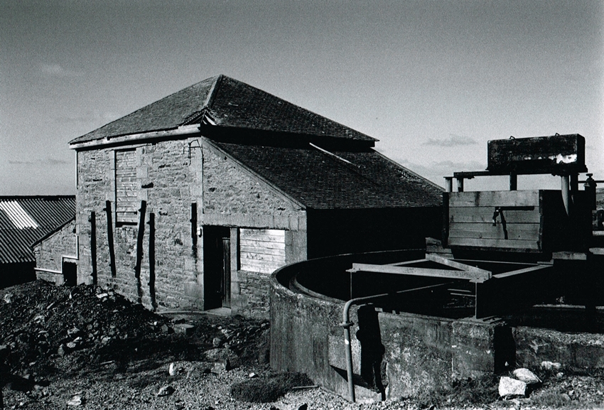
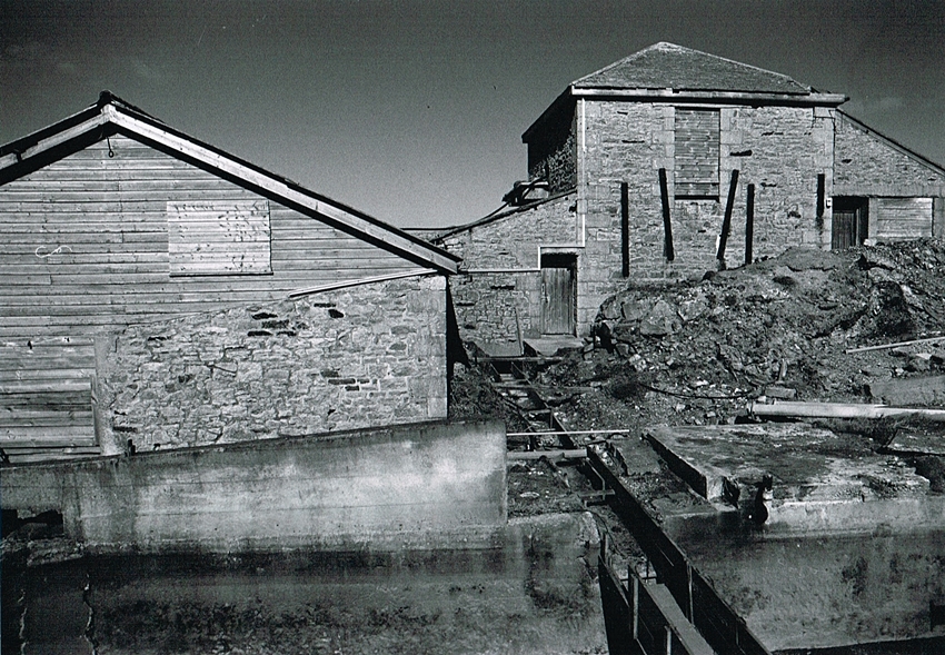
Geevor Tin Mine Gallery 3.3 – This image shows both the Calciners.
The bracing on the Calciner walls is to reinforce the walls from the heat inside. The western Brunton calciner in the foreground, and the eastern in the distance. The eastern Calciner interior has had the rotating hearth & rabble bars removed, also a concrete floor laid. It was here that an experimental “Buckman” frame was installed together with experimental hydrocyclones under the supervision of Doctor Birch & Mr Simms.
geevor tin mine gallery 3
Geevor Tin Mine Gallery 3.4 – A closer image of the eastern Calciner. Also the building on the left of the image is the Slimes Plant.
geevor tin mine gallery 3
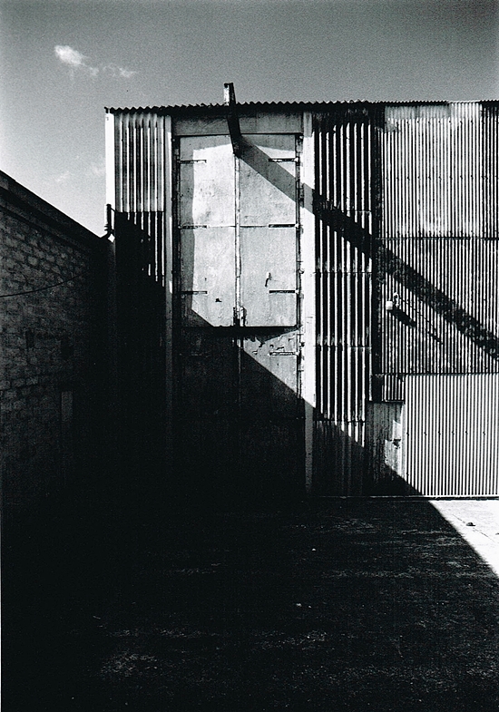
Geevor Tin Mine Gallery 3.5 – The Eastern Bruton Calciner. The right hand door goes into the “Buckman” house refereed to above. Left hand door is the access door into the “Slimes plant”. Also known on the mine and to locals as Wembley. The Slimes plant was the last process,  treating the very fine material from the mill.
geevor tin mine gallery 3
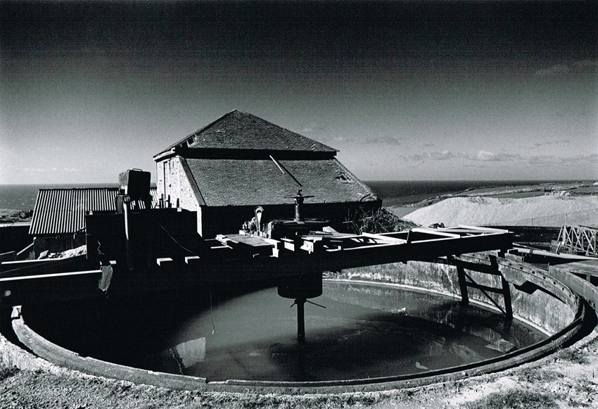
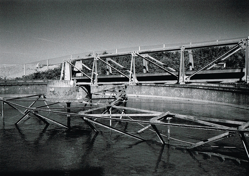
Geevor Tin Mine Gallery 3.6 – This is the 35′ round tank.
The round tank was a “thickener”, it contained slowly rotating rakes that continually scraped settled solids to the conical centre of the tank. The revolving rakes were driven by a worm drive mechanism supplied by R.O.Stokes. The mechanism had a very large spring on the worm drive shaft.
As the bed of settled solids built up the thrust on the spring increased and allowed it to push sideways tripping a micro switch, illuminating a lamp and ringing a bell. An operator would then manually raise the rakes or increase the rate of extraction of solids. The supernatent flowed on to a larger thickener, the 70′ tank. Just as a matter of interest, I fitted all new rakes, steel beams & overhauled the drive mechanism during the 1975 summer maintenance shutdown.
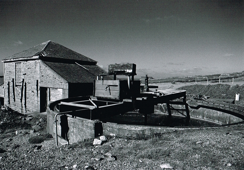
New Geevor Mine Gallery 3.7
Geevor Tin Mine Gallery 3.7 – A second wider image of the Tank and Eastern Calciner. The large hand wheel above drive mechanism was for manually raising the rakes. The thickener could be used to store fine settled fines by continually raising the rakes. Then to reclaim this stored material the rakes would be slowly lowered.
geevor tin mine gallery 3
Geevor Tin Mine Gallery 3.8 – A final image of the tank, the sector shaped object standing up to left and below the centre hand wheel is the torque / load sensing indicator.
geevor tin mine gallery 3
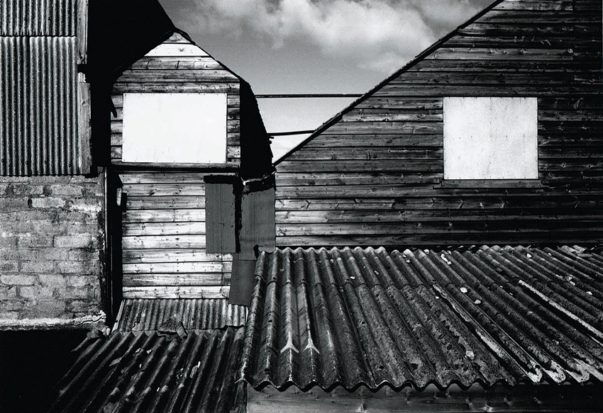
Geevor Tin Mine Gallery 3.9 – Textures and patterns, light and dark in this image.

The building to left is the “Bottom fitting shop” which was the Maintenance shop for the mill. Also to the right this was the “HMS Plant”, Heavy Media Separation. Basically this plant used a slurry containing a mixture of atomised ferro silicon and magnatite at a density of 2.7 SG.
Run of mine rock was fed into it, if the rock was more that 2.7 SG it sank then collected as mineral bearing rock for further processing. If the rock was less than 2.7 SG it floated, was collected then sent to be screened as aggregate.
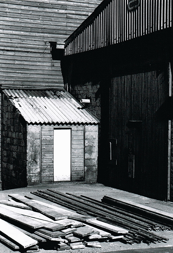
geevor tin mine gallery 3
Geevor Tin Mine Gallery 3.10 – The building on right was the “Bottom fitting shop” or mill maintenance shop.
geevor tin mine gallery 3
Geevor Tin Mine Gallery 3.11 – This is one of my favorite images on this page, black and white makes the detail jump out.
geevor tin mine gallery 3
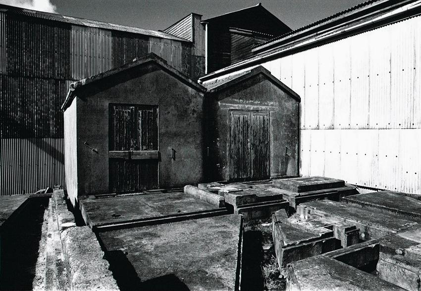
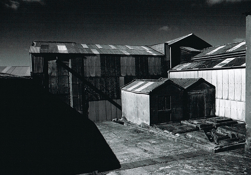
Geevor Tin Mine Gallery 3.12 – These are the Mill electrical switch rooms, large 11,000 Volt to 440 Volt 3 phase transformers stood on the concrete plinths. The building behind the switch rooms is the HMS plant. Earlier it contained a “Wemco” drum separator & later a “Tri-Flow” separator. To the right was the “Washing plant” containing a “Wild” washer/scrubber, Symons cone crushers, also a  picking belt and conveyor belts.
geevor tin mine gallery 3
Geevor Tin Mine Gallery 3.13 – Another of the same buildings from a distance.
geevor tin mine gallery 3
Geevor Tin Mine Gallery 3.14 – This image is the 70′ tank.
Again this is a R.O Stokes revolving thickener. Except that it is a “space-frame” with three bogies running on a circular track around the perimeter of the tank. One of the bogies being powered. The power supply running through a cable along the bridge to the center where there is a set of triple slip-rings & carbon brushes. This device allows the power to reach the driven bogie.
Cornish Mines Images
Geevor Tin Mine Gallery 3.15 – A panorama of the lower buildings on the site, in the centre is the 70′ tank. Also notice the side of the eastern Brunton Calciner. A ramp leading up from the left and a cantilevered track. This would have been for charging the Calciner with ore.
Cornish Mines Images
Geevor Tin Mine Gallery 3.16 – The 70′ Tank. Again this is a R.O Stokes revolving thickener. Except that it is a “space-frame” with three bogies running on a circular track around the perimeter of the tank.
Cornish Mines Images
Cornish Mines Images 3.17 – “Mintech” on stream analyser building, photographed from building that housed a sand pump.
Cornish Mines Images
Cornish Mines Images 3.18 – On the left was a concrete building housing the Mintech on-stream analyser.
Mintech on-stream analyser, this was a method using radio active isotopes to detect to % of tin contained in various tailing streams. The tailings pulp stream was continually scanned. If the readings were outside of predetermined parameters alarms sounded.
The building on the right housed a sand pump. This was used when required to pump tailings to a hydrocyclone up on a timber structure & create a pile of sand. This sand was used by the mine masons for all building work. Also local builders would come to the mine for sand.
Cornish Mines Images
Cornish Mines Images 3.19 – The bunker type building with pipes entering through the roof housed the “Mintech” on stream analyser. There were compressed air operated valves that were activated by timers that opened “linatex” valves to run the selected tailings stream through the analyser.
Cornish Mines Images
Cornish Mines Images 3.20 – Finally, looking back towards the Slimes plant

Geevor Tin Mine Gallery 4

Contact

error: Copyright Simon Jones 2022