Geevor Tin Mine Gallery 1: I first saw the Geevor Tin Mine during 1992. The pumps had been turned off for about a year also the scrapmen had moved in to strip the buildings of anything of value. Thankfully the community persuaded the local council to buy the site and preserve it. I was so lucky being allowed to roam the site before the museum fully opened to take many photographs. This was during 1993/4, my thanks go to Tony Brooks who was involved at the time.
The information on these and the images to follow have been supplied by My Bob Orchard. He was the Chief Engineer and became Mine Manager on closure. Much of his time after the mine closed was spent campaigning to save the site and also keep vandals and souvenir hunters at bay.
Geevor Tin Mine is now a museum dedicated to the history of the mine and Cornish Hard Rock Mining. It is certainly worth a visit, a link to their website is below.
The images on this first page cover Victory Shaft and the area around it.


To do this one of the sheave wheels (lying on their side in foreground) was placed just inside of the shaft gates and the rope reeved off the wood drum. It went up to the top and over the sheaves of the Victory headframe onto the drum of the steam winder. Then the process set up again off the steam winder, under the temp sheave up over the top of the headframe then down onto the electric British Thomas Houston winder.
It was always a big day. On the right is a solitary Stokes type YR sand pump. Just as a matter of interest, the reason that these sheave wheels are still at Geevor is because I buried them in the gravel pile at a point that I had coordinates for and could retrieve them at a latter date. Otherwise they would have been sold off as a “cash in the pocket” job by the scrapie’s men.
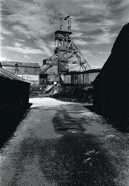
The building on right is the old stables. This later to become the mine store until the store moved into the building that is now the shop. In those days the head storeman was Jim Vincent.
Building on left was a lean-to the carpenters shop & housed a machine for making wooden spacers for blasting underground. It produced a rough, round dowel rod about one inch Diameter. Also a source of broom hilts on the mine. The machine was made by Clifford Trezise.
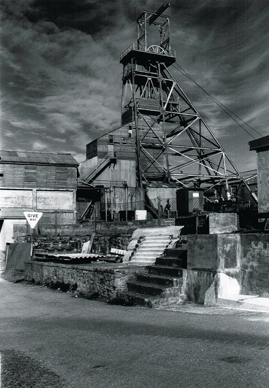
The steps lead up to the “Square pool” the reservoir for the mill. Leaning up against wall is a “Wilfly” shaking table deck. Just as a matter of interest (so I have been informed) the scrap man were living on site in a mobile home. One evening a couple of local characters picked up the portable generator for the mobile home and threw it into the Square pool. Remains of which were found a few years ago when the pool was drained.
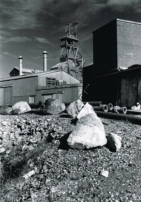

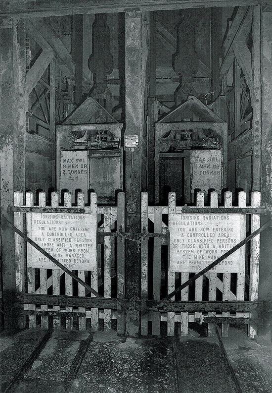
Cages sitting on “keps” (some call them “chairs”) on the change-over gantry. Note the “King Hooks” (Reliance Barker Davis detaching hooks) attaching the cages to the winding ropes (1 & 1/8″ Dia left hand Laings lay wire ropes). The detaching gear engaged with the detaching “ring” high up in the headframe in the event of an over-wind. A copper pin would shear, the hook wings open & latch onto the detaching ring while at the same time releasing the winding rope.
The detaching hooks were changed ever three months (the spare set fitted & the ones just taken out of service sent for crack testing & re-certification). Every six months six feet of wire rope would be cut off & sent for test. The end the the rope re-caped with molten white metal. Every three years the complete wire rope would be replaced with new. Eimco Muckers & loco’s were hoisted in the cages, while heavier and larger items were slung below the cage. The sloping canopy over each cage could fold back & a false floor fitted to the top of the cage for the shaft master (Eric Gale & his assistant Norman Barnecote) to ride on top of the cage to inspect the shaft, shaft setts & runners.
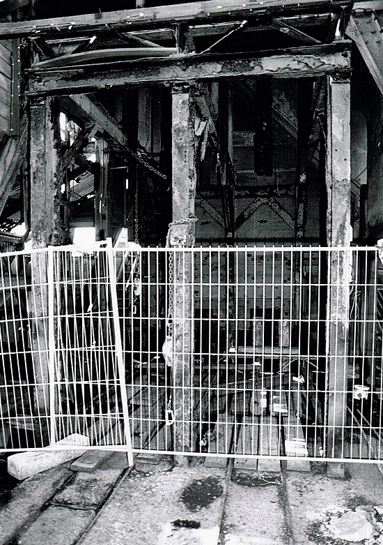
The structure here was known as the “Gantry”. It was designed by Bennett Wall the then chief engineer, when the new BTH winder was installed. During normal operation the cages ran through the gantry with two rock skips to the rear sitting on “keps”. When changing from cages to skips the cages (one compartment at a time) were lowered onto keps (stops), the gantry pushed forward to bring the skip over the open shaft. The winding rope removed from the skip & attached to the skip. The skip lifted slightly to enable the kep to be folded back into the runner. Then repeated for the other shaft compartment.
When the mine closed I had the cages both put onto the keps effectively blocking the shaft. At the time considered a temporary measure as there were possible rescue plans for the mine. However, as time went on it was apparent that this was not going to happen.
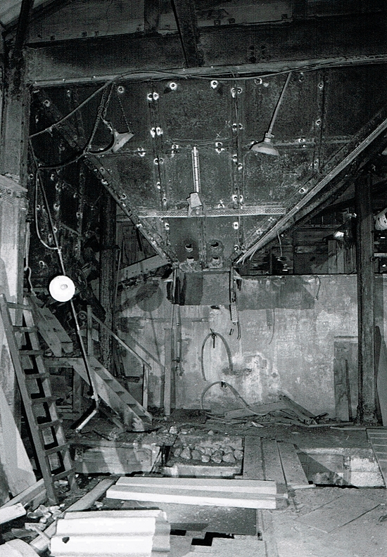
The series of round hole in the coarse rock bin were for a crow bar if there was a jam up of rock in the mouth of the chute. Under the fines bin was a very short variable speed feeder conveyor. This discharged the fines down a chute to provide a protective layer on the conveyor that ran to the “washing plant” .
This short feeder conveyor was particularly difficult to “track”. The bottom of the slot in the floor running left to right was quite deep, dark and wet. Also it housed the tail drum of the conveyor to the washing plant. We had to go down here to renew chute liners, tension and adjust the conveyor to the washing plant. It was known as “black hole chute” or “Annies room”
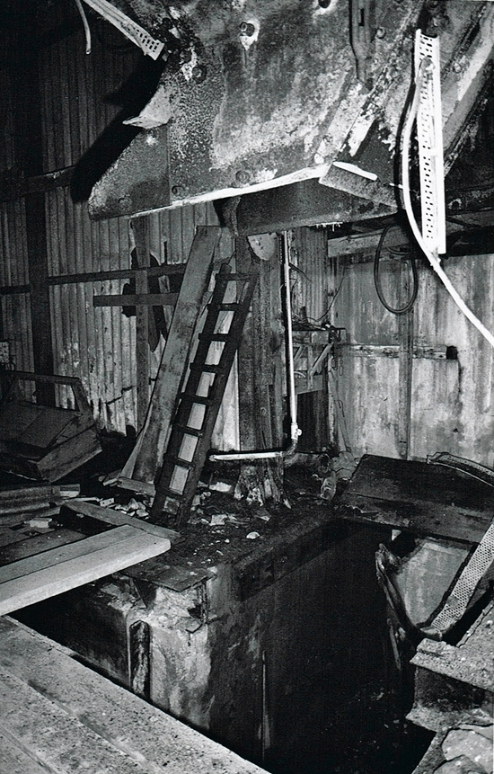
The slot in the floor to the left sat under the crusher, it had a chute that fed the crushed rock down onto a conveyor belt that conveyed the ore to the “Wild” rotary washer. The other slot extending away from the camera picked up the “Fines” that did not require crushing. These were deposited onto the conveyor to the washer. This layer of fines was important, as it protected the conveyor belt surface from the larger pieces of crushed rock sliding down the chute from the jaw crusher.
The steel chute above is the bottom of the “Course rock bin”. Here there was a variable speed vibrating tray feeder that fed the rock into the mouth of the jaw crusher. Just as a matter of interest, the Kueken crusher was the very first piece of equipment removed from the mine. So, I actually assisted Arthur Roby (the scrap man) to slide this heavy item off from it’s RSJ supports and got it to the door.
Then it was loaded into a tipper truck of some contractors from Ireland. It was not secured in any way and the truck set off for the ferry. Later I heard that the truck had gone around a roundabout too fast, the crusher slid sideways tipping the truck over on its side. Ho Ho!


The Round tank gravity fed the more critical items of plant in the mill. To the left of the tank can be seen a rectangular steel box with a 4″ pipe coming out of it, these boxes were strainers. When there was surplus water being pumped to the round tank it overflowed to the “Square pool” on the opposite side of the road. The round tank also supplied water back down Victory shaft for the rock drills. There being pressure regulators at intervals down the shaft to prevent excessive pressure.

Daily requirement of explosives were transferred from the mine explosives magazine to the transit store. Then the “cage man” would distribute to the various shaft stations for the mining crews to use.


