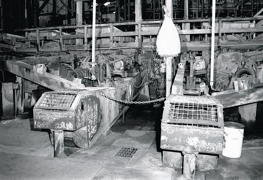
Geevor Tin Mine Gallery 9

Geevor Tin Mine Gallery 9: This page contains images of the Geevor Western Calciner. Once again Bob Orchard has supplied much of the information.

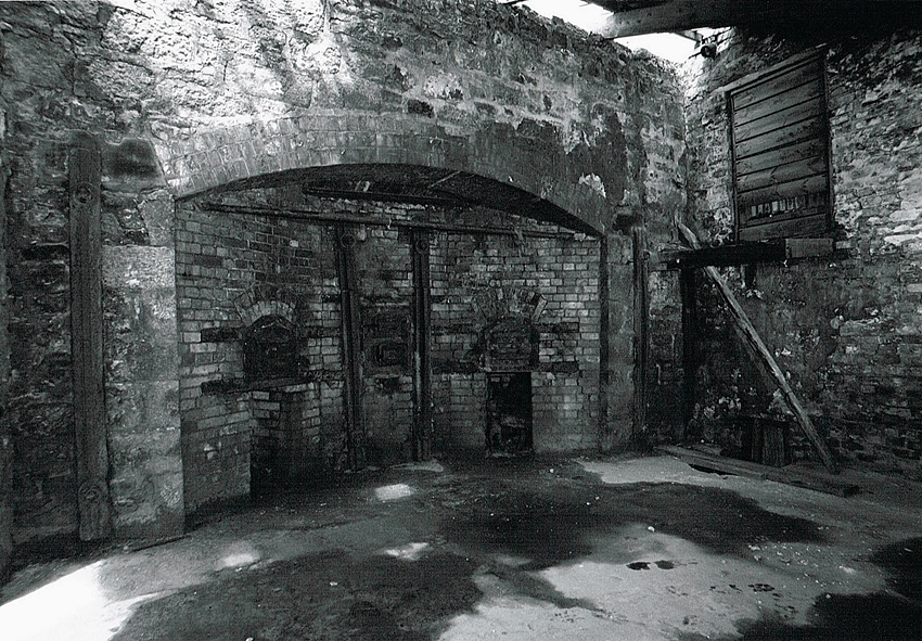
The Calciner was used to roast Tin Ore to remove Arsenic. This was an impurity, but if recovered it was sold on as a valuable by-product. The ore was loaded from the second floor of the building onto a slowly rotating hearth, this ensured the material was evenly heated. Beneath this were the furnaces, these would heat the ore to a stage where the impurities were released.
Geevor Tin Mine Gallery 9
Geevor Tin Mine Gallery 9.1 – Geevor western Brunton Calciner. The two doors were for the removal of the roasted tin concentrate. The arsenic having been roasted out.
The Arsenic was released as a vapour, this would condense is a long flue leading to a chimney. Workers would then remove the Arsenic from the flue where it would be bagged up and sold on. This was not a pleasant job without protective clothing.
Geevor Tin Mine Gallery 9
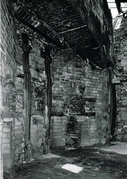
Geevor Tin Mine Gallery 9.2 – Another image of the Geevor western Brunton Calciner.
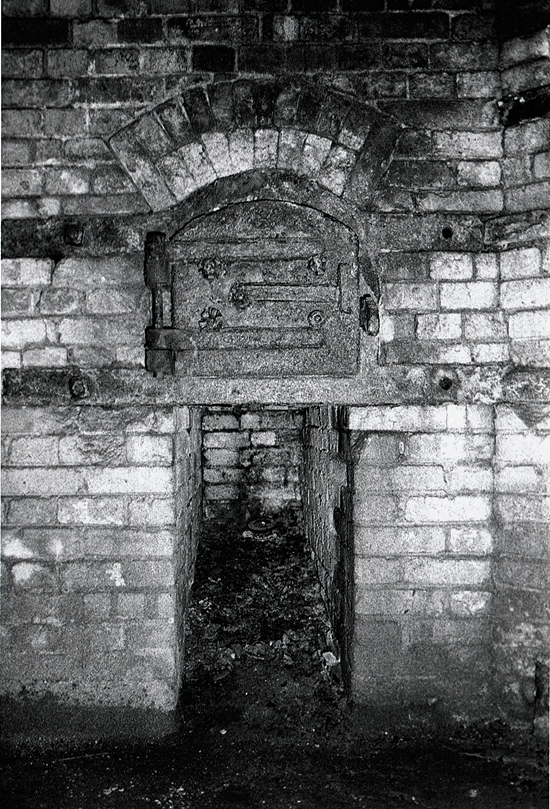
Either side of the roasted tin concentrate removal doors were the fire boxes where the fire burnt with the flames running over the rotating hearth of the calciner. Typically the hearth would make between 4 to 6 revolutions per hour. It is in reality a reverburatory furnace with a rotating bed.
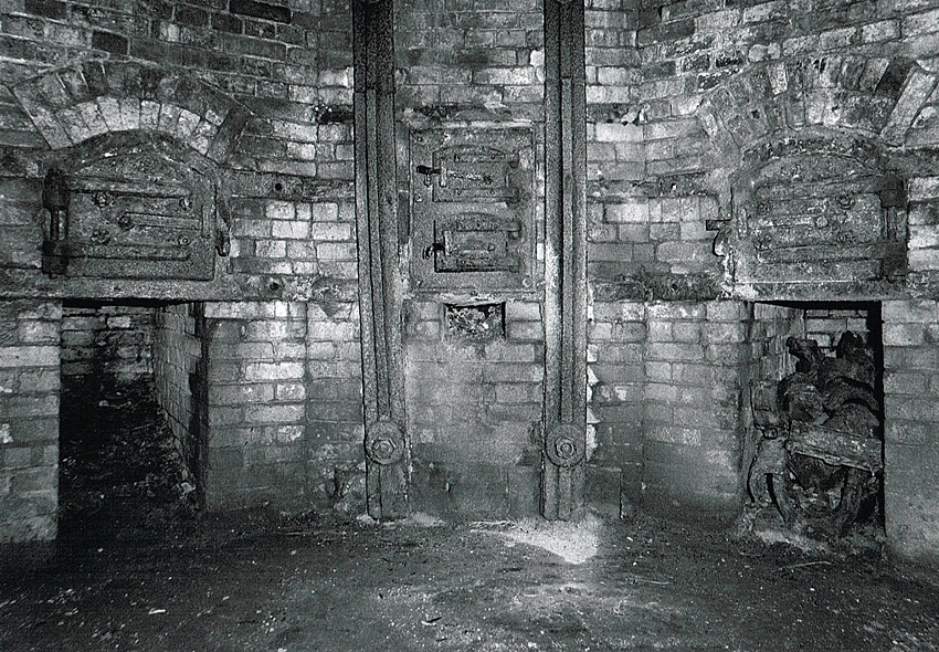
Tin concentrate was fed onto the rotating hearth from above. As the hearth rotated “rabble bars” raked & scraped the roasted concentrate. When the operators deemed it to be free from arsenic it was raked with long iron scrapers out through the central doors.
I believe that this calciner did not have a Labyrinth condenser for the arsenic. But discharged the arsenic fumes direct to atmosphere.
Geevor Tin Mine Gallery 9
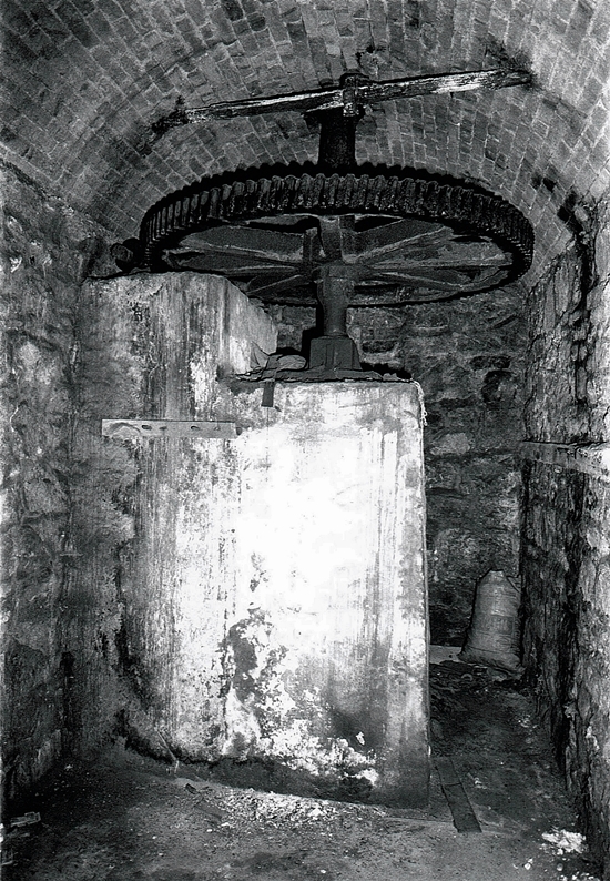
Geevor Tin Mine Gallery 9.3 – Geevor western Brunton Calciner.
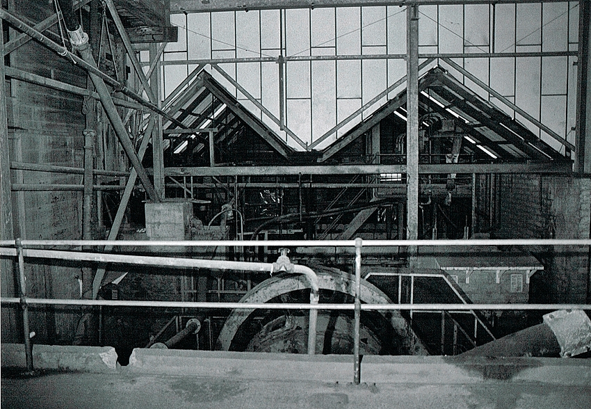
Below the calciner was the mechanism to rotate the hearth. Consisting of a vertical shaft which was keyed to the central hub of the hearth and the large worm-wheel in the picture. To the left and in line with the worm wheel is the worm and a short stub of shafting that drove the worm.
The hearth, shaft, worm-wheel & tin concentrate being roasted would be of considerable weight. The thrust of this being taken by the foot-step bearing at the bottom of the vertical shaft. The speed of rotation of the hearth would typically be around 4 to 6 revolutions per hour.
Geevor Tin Mine Gallery 9
Geevor Tin Mine Gallery 9.4 – Geevor western Brunton Calciner. Right hand fire hole door, with opening below for the ashes & clinker.
Geevor Tin Mine Gallery 9
Geevor Tin Mine Gallery 9.5 – Geevor western Brunton Calciner. The fire holes & the central roasted ore removal doors.
Geevor Tin Mine Gallery 9
Geevor Tin Mine Gallery 9.6 – Geevor western Brunton calciner. The fire holes & the central roasted ore removal doors. Note the two vertical “strong-backs” that hold the structure together.
The remaining images on this page are all taken in the “New Table Plant” and sections of the “Old Mill”. The Geevor Mill was where the rock mined underground went for processing. The average grade recovered at Geevor was approximately 1%, but this meant that 99% of the rock removed was waste. This was often sold on for road making material.
Underground the ore had been put through the crusher so it was easier to transport up the shaft. Once at surface the rock was further ground in Ball and Rod mills, every time the rock got smaller more of the Tin particles were released from the bulk. These particles were removed in the processing mill and were sold as Tin Concentrate, over 50,000 Tons were recovered in this way.
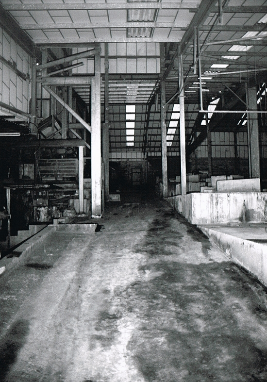
Geevor Tin Mine Gallery 9
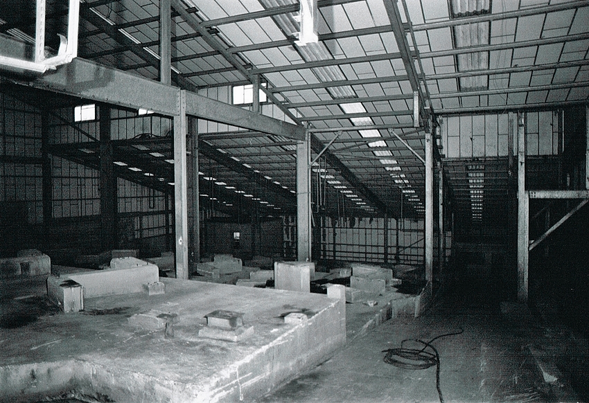
Geevor Tin Mine Gallery 9.7 – New table plant, looking up the access ramp that runs alongside the old Geevor mill. By this time all the Holman shaking tables have been removed. So many got damaged in the removal process by the scrap men. It is debatable that the labour costs to remove them would have been cost effective.
Geevor Tin Mine Gallery 9
Geevor Tin Mine Gallery 9.8 – New table plant, looking down the access ramp that runs alongside the old Geevor mill. (Old mill on right)
Geevor Tin Mine Gallery 9
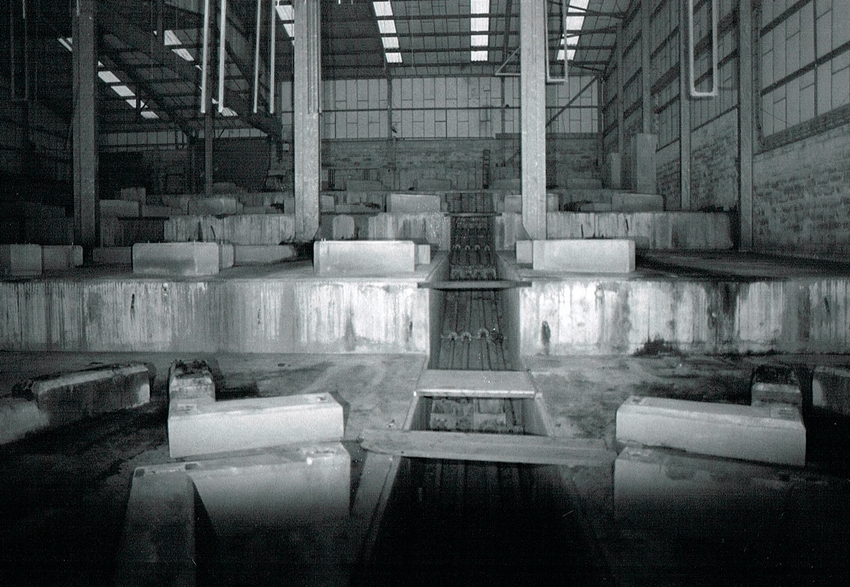
Geevor Tin Mine Gallery 9.9 – New table plant, looking up the western side. Note the pipe & services trench. Also the distinctive concrete shaking table foundations that can be seen on many mine sites.
Geevor Tin Mine Gallery 9
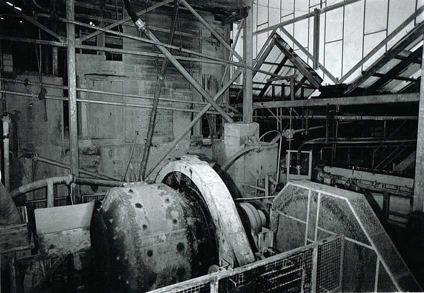
Geevor Tin Mine Gallery 9.10 – Geevor old mill. Looking over the top of the old primary cylindro-conical Ball Mill. This was a “Hardinge” mill. In the early days it was lined with manganese steel liners. But by the time this photo was taken it was lined with Trelleburge rubber ……much easier to install as well as making the mill quieter.
Geevor Tin Mine Gallery 9
Geevor Tin Mine Gallery 9.11 – Another image showing the Ball Mill in more detail.
Geevor Tin Mine Gallery 9
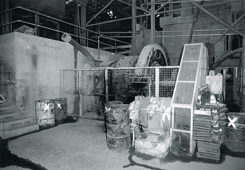
Geevor Tin Mine Gallery 9.12 – Geevor old mill. Hardinge cylindro-conical ball mill. Note the slip ring motor that drives it. The drums contain manganese steel “balls” for charging the ball mill.
Geevor Tin Mine Gallery 9
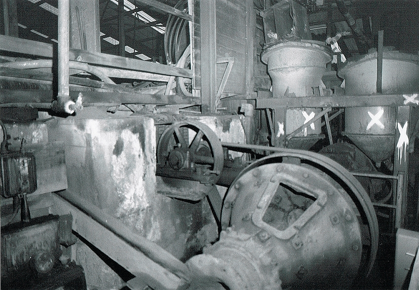
Geevor Tin Mine Gallery 9.13 – Geevor old mill. To the east of the first stage of batch froth flotation, a small cylindro-conical ball mill with a tube mill to it’s right.
Geevor Tin Mine Gallery 9
Geevor Tin Mine Gallery 9.14 – Geevor old mill. “Third floor” single acting rake classifiers with a R. O. Stokes YR vertical spindle pump between them at rear.
The rake classifiers are fed with “middling’s” from the shaking tables, the coarse particles settle and are scraped up then fed into the ball mills to be re-ground. The fine material over-flows, and re-joins the material discharging from the ball mills. This prevents over grinding also reduces the production of “slimes”.
Cornish Mine Images
Cornish Mine Images 9.15 – Geevor old mill. “Third floor” shaking tables with there middling’s re-grind ball mills below.
Cornish Mine Images
Cornish Mine Images 9.16 – Geevor old mill. Top end of the “tin Floors” shaking table foundations.
Cornish Mine Images
Cornish Mine Images 9.17 – Geevor old mill. Top end of the “tin Floors” shaking table foundations.
Cornish Mine Images
Cornish Mine Images 9.18 – Geevor old mill. Holman shaking tables in what was also known as the “Vanner house”.
When I first visited the mine in about 1963 it was full of Frue Vanners all driven by flat belts from line shafting. In 1965 I helped to run cables & wire up these Holman shaking tables.
It was a school visit to the mine organised by our metal work teacher Tom Prouse that started my interest in Geevor & mining in general……….So it was all Tom Prouse’s fault!!
Cornish Mine Images
Cornish Mine Images 9.19 – Geevor old mill. “Third floor” re-grind ball mills with single acting rake classifiers between them.
Cornish Mine Images
Cornish Mine Images 9.20 – Geevor old mill. A R.O. Stokes multi-spigot hydrosizer. This devise hydraulically classifies mineral sands according to their settling characteristics in an upward column of water. By doing this it improves the efficiency of the shaking tables.

Geevor Tin Mine Gallery 10

Contact

error: Copyright Simon Jones 2022