South Crofty Robinsons Engine House 2

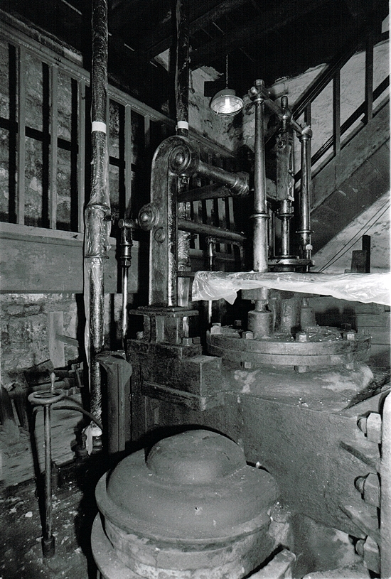
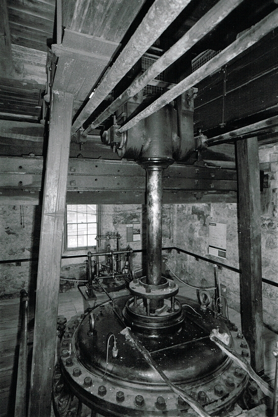
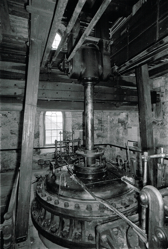
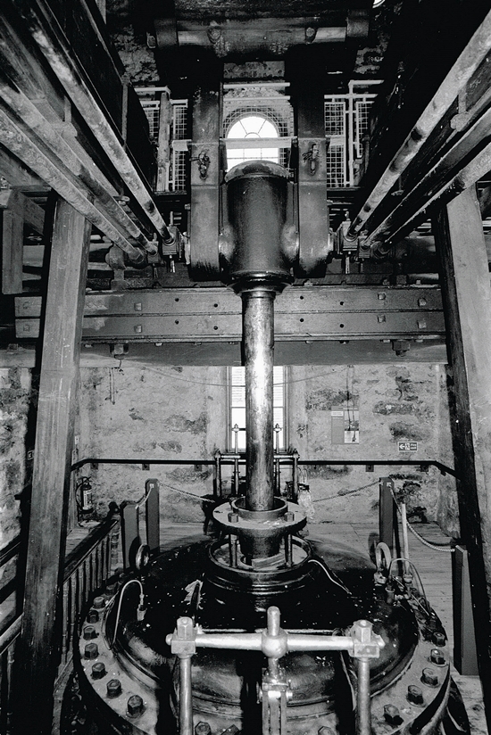
Robinsons Engine House 2: The images on this page are all taken in the middle chamber of the engine house. On this floor are the valve chests and the top of the cylinder.

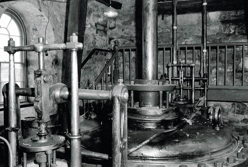
This engine is unique in respect that it has two valve chests, one for live and the other for equilibrium steam. The idea behind this was to minimize heat loss from the live steam when it passed over the surfaces cooled by the outgoing steam.
Robinsons Engine House 2
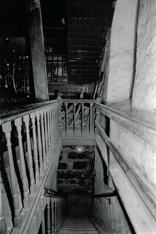
South Crofty Mine Robinsons Engine House 2.1 – Looking back down the well worn stairs to the floor below.
Robinsons Engine House 2
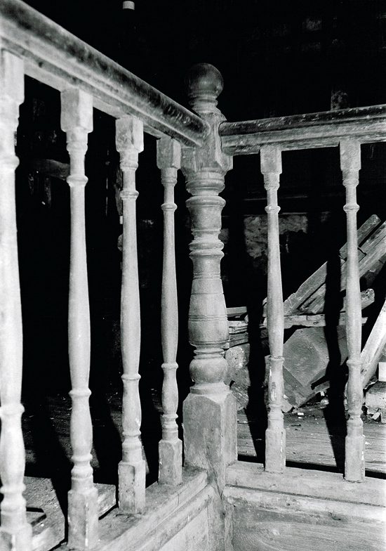
South Crofty Mine Robinsons Engine House 2.2 – The banisters and the newel post surrounding the staircase. Like all engine houses the interior would have been kept clean. The engine would be gleaming also all the decorative features would reflect the mines prosperity.
Robinsons Engine House 2
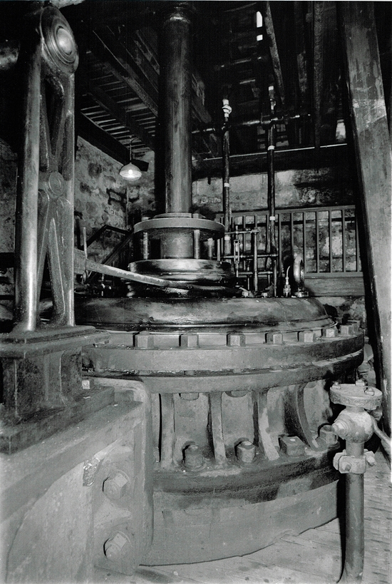
South Crofty Mine Robinsons Engine House 2.3 – The first view of the cylinder head and the piston.
Robinsons Engine House 2
South Crofty Mine Robinsons Engine House 2.4 – Both sets of valve chests can be seen in this image. One either side of the cylinder cover.
Robinsons Engine House 2
South Crofty Mine Robinsons Engine House 2.5 – A more detailed image of the “equilibrium” valve chest.
Robinsons Engine House 2
South Crofty Mine Robinsons Engine House 2.6 – This is the “live” steam valve chest above the drivers position.
Robinsons Engine House 2
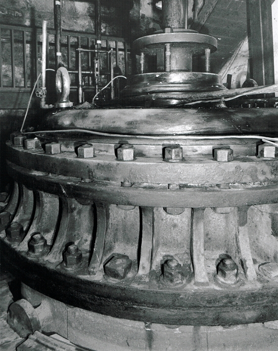
Cornish Mine Images 2.7 – The top of the cylinder with the fixing bolts.
Robinsons Engine House 2
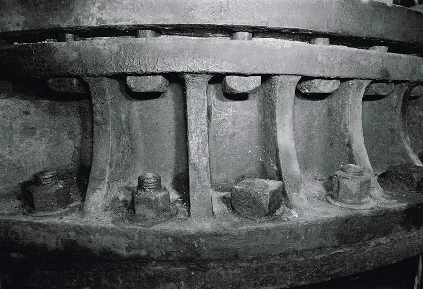
Cornish Mine Images 2.8 – The ornate bolts around the top of the cylinder are designed to hold the cover firmly in place. Also an amazing attention to detail.
Robinsons Engine House 2
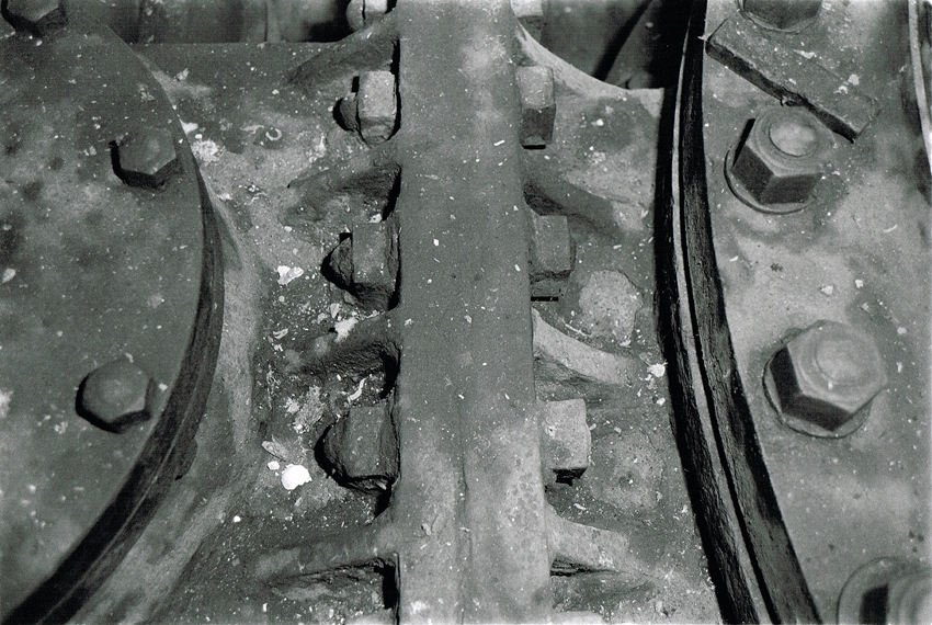
Cornish Mine Images 2.9 – The heavily bolted connection to one of the valve chests
Robinsons Engine House 2
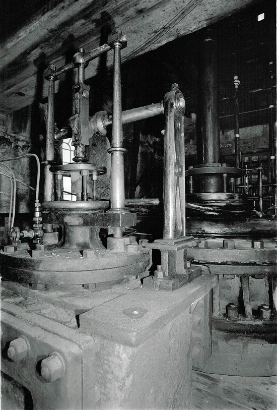
Cornish Mine Images 2.10 – The top of the piston rod, the horizontal arms are for the parallel motion. Invented by James Watt during 1808. This enabled the force of the engine to be transmitted in both directions while the piston rod was held vertical.
Robinsons Engine House 2
Cornish Mine Images 2.11 – The timber uprights helped to support the weight of the beam on the floor above.
Robinsons Engine House 2
Cornish Mine Images 2.12 – A good view of the top of the piston rod showing the attached arms.
Robinsons Engine House 2
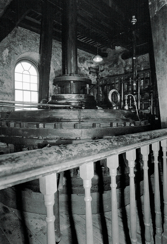
Cornish Mine Images 2.13 – Looking across the cylinder head to the raised balcony behind.
Cornish Mine Images
Cornish Mine Images 2.14 – This image taken using a very wide angle lens shows the whole of the middle chamber of the Engine House.
Cornish Mine Images
Cornish Mine Images 2.15 – Middle chamber looking back from the balcony. The main girder holding the floor above runs from left to right. This comprises of six pieces of 18″ square timber bolted together.
Cornish Mine Images
Cornish Mine Images 2.16 – Each part of the engine had been beautifully made.
Cornish Mine Images
Cornish Mine Images 2.17 – This is the top of the “equilibrium” valve chest.
Cornish Mine Images
Cornish Mine Images 2.18 – The top of the piston rod. Also the parallel motion arms connected to the rod can be clearly seen.
Cornish Mine Images
Cornish Mine Images 2.19 – A final view of the cylinder head from the balcony leading to the next set of stairs. This is directly above the drivers position on the floor below.

South Crofty Mine – Robinsons Engine House 2016: 3

Contact

error: Copyright Simon Jones 2022