Parkandillick Gallery 1

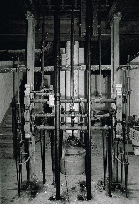
Parkandillick Gallery 1: This page has images taken on the first floor of the Parkandillick Engine House. On walking through the door the first thing seen is the base of the cylinder.
Parkandillick Gallery 1
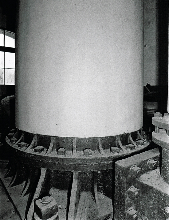
Parkandillick Gallery 1.1 – Firstly, an image of the 50″ Cylinder of the engine showing the ornate fixing bolts.
The engine is single-acting and fitted with a jet condenser. This is outside between the house and the shaft, with the air pump and feed pump to the boiler driven from the beam. Steam acts on the top of the piston. In turn this is aided by vacuum from the condenser beneath.
Parkandillick Gallery 1
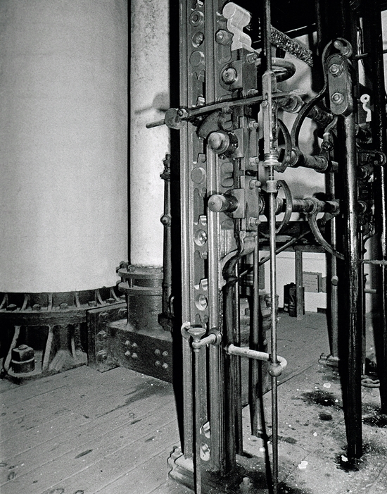
Parkandillick Gallery 1.2 – The drivers position, in the background the cylinder.
This pulled the indoor end of the beam down, raising the pump rod, also the plunger in the shaft. The return stroke was effected by the weight of the pump rod. Part of the weight was also counteracted by a balance box to ensure smooth operation. The engine did about six strokes per minute also lifting 125 gallons of slurry at each stroke.
Parkandillick Gallery 1
Parkandillick Gallery 1.3 – The engine has a single perpendicular pipe connecting the two ends of the cylinder.
The present cylinder is a replacement made by Bartle’s Foundry, Carn Brea. This was required when the engine was moved. It currently lacks a steam jacket. Steam was supplied by a single Lancashire boiler which also still remains in the Boiler House.
Parkandillick Gallery 1
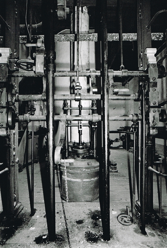
Parkandillick Gallery 1.4 – A close image of the ornate drivers position.
Until recently the engine was run while under air pressure. This was supplied by a two stage centrifugal fan, delivering 700 cu.ft.of air per minute. Because the engine requires a load to operate, the top sections of the pump rod were retained when the pitwork was dismantled. Consequently, the nose of the beam weighs in at around a ton. (Courtesy of The Trevithick Society)
Furthermore, the engine was known fondly as Elizabeth by those who worked her.
Parkandillick Gallery 1
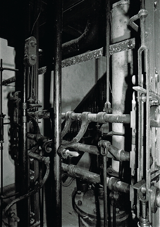
Parkandillick Gallery 1.5 – Another detailed image of the various handles and levers the driver would use to control the engine.
Parkandillick Gallery 1
Parkandillick Gallery 1.6 – This is the drivers view looking into the Engine House.
Parkandillick Gallery 1
Parkandillick Gallery 1.7 – There is a delicate chain holding the bottom (exhaust) handle down and this would be released to start the engine. The engine is worked by hand for several strokes until the vacuum is stable and the stroke length has settled down. It is then subsequently put on the cataracts and becomes self-acting.
Under steam the engine would have been started by hand. Achieved by using the long handles to work the valves until full vacuum was reached in the condenser. Under air, the controls were left set, the engine started itself once working air pressure was reached.
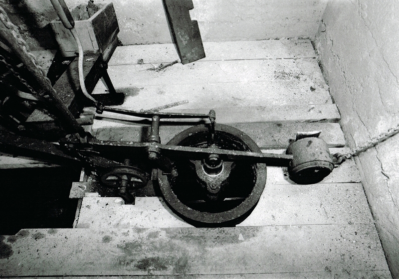
Finally, the stroking of the engine was controlled by two water-filled cataracts beneath the floor, just as when in steam. (Courtesy of The Trevithick Society)
Parkandillick Gallery 1
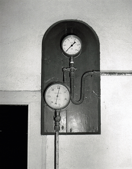
Parkandillick Gallery 1.8 – Pressure gauges mounted on the wall close to where the driver stood.
Cornish Mine Images
Cornish Mine Images 1.9 – Below the driving position is known as the Cataracts Pit. In the background is one of the cataracts. This uses water forced through an adjustable orifice to time the pauses between strokes. In the centre is a weight box. This operates to open one of the engine’s three valves under gravity.
Cornish Mine Images
Cornish Mine Images 1.10 – In the centre is the bottom of the plug rod. This operates the valves and sets the cataracts between strokes.
Cornish Mine Images
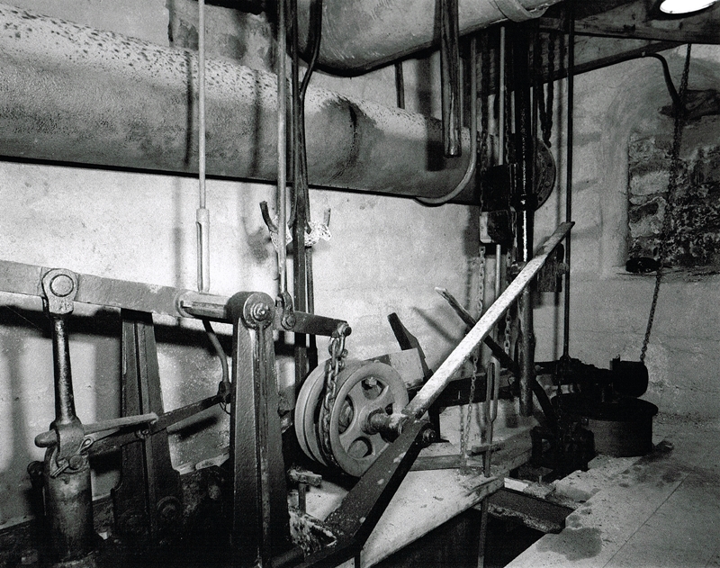
Cornish Mine Images 1.11 – In contrast to the size of the engine, delicate balance and controls are needed to keep it running smoothly.
Cornish Mine Images
Cornish Mine Images 1.12 – A final image of the balancing gear. Under the wooden floor it was full of oil and water.
Extra information sourced from www.geograph.org.uk

Parkandillick Engine House Gallery 2

Contact

error: Copyright Simon Jones 2022