The Levant Mine Beam Engine, this page covers not only the engine but other features that are not covered in the other pages. My thanks to my friend Ryan Thomas for taking time out to show me around. Also my thanks to Paul Smith one of the members of the Greasy Gang, he has supplied some of the information on this page.
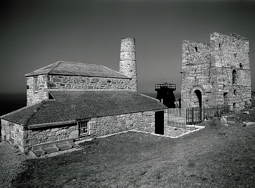
There are two shafts in this area, with just a few feet of rock between them. Skip Shaft for Winding and Engine Shaft for pumping. Both were sunk to 290 fathoms below adit (1740 ft). However for the total depth of both shafts the cliffs here are about 200ft high. So this has to be added to the depth below adit.
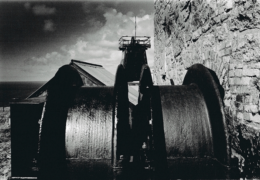
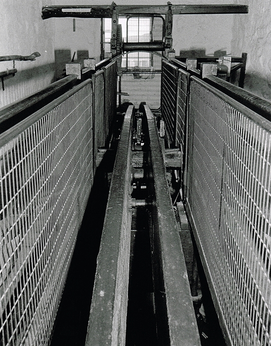
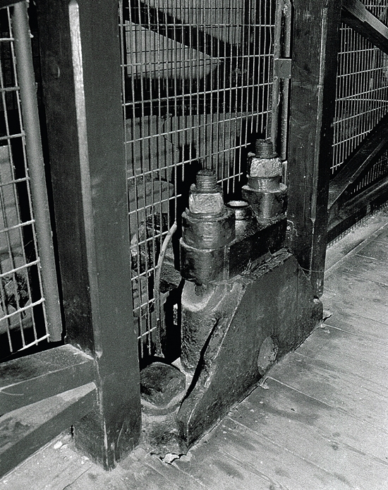
The preserved engine is a Whim Engine, this was used to lower and raise men and materials in Skip Shaft. Built during the 1840’s by Harvey and Co of Hayle. It is a double acting beam engine in an enclosed house, sadly the only engine powered by steam in its original house in Cornwall.
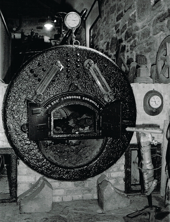
This fine survival was designed by Francis Michell, equipped with a 24″ cylinder it was primarily used to draw ore up the shaft from 1700ft below grass. The ore skips were of 1-ton capacity. The engine worked at a speed between 40-50 rpm, this was approximately 400ft per minute. When fully loaded each to trip to the surface would take over 5 minutes.
The engine worked at the mine until 1930 when Levant finally closed. The mine never really recovered from the Man Engine disaster of 1919 when 31 miners perished. After the accident the mines lowest levels were lost. After closure all the mine machinery sat idle in the hope of a reopening. Several year later in 1934 the scrap men started to strip out anything of value.
A team of enthusiasts headed by Jack Trounson attempted to save the ancient pumping engine. Cash was needed, by the time the group had raised some capital the engine had been already scrapped. By chance the whim remained, although the dismantling had already started. So they purchased that, and the engine was saved.
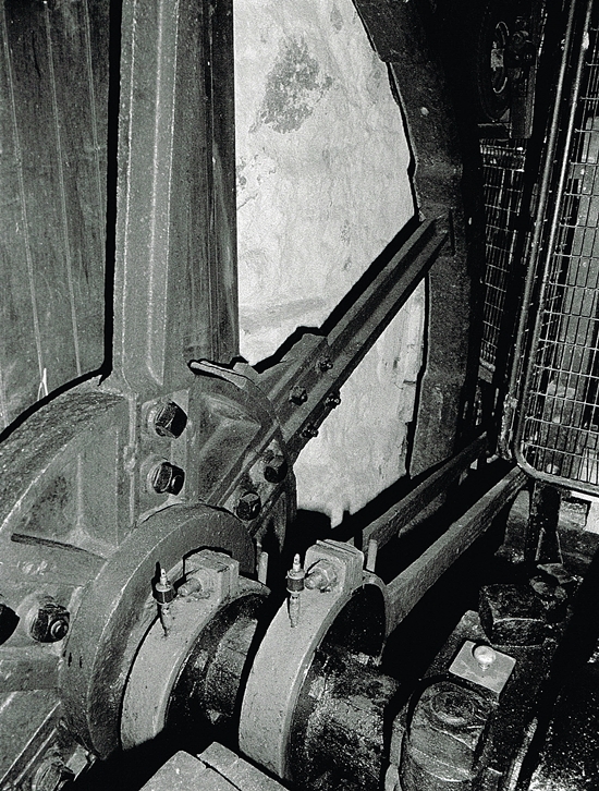
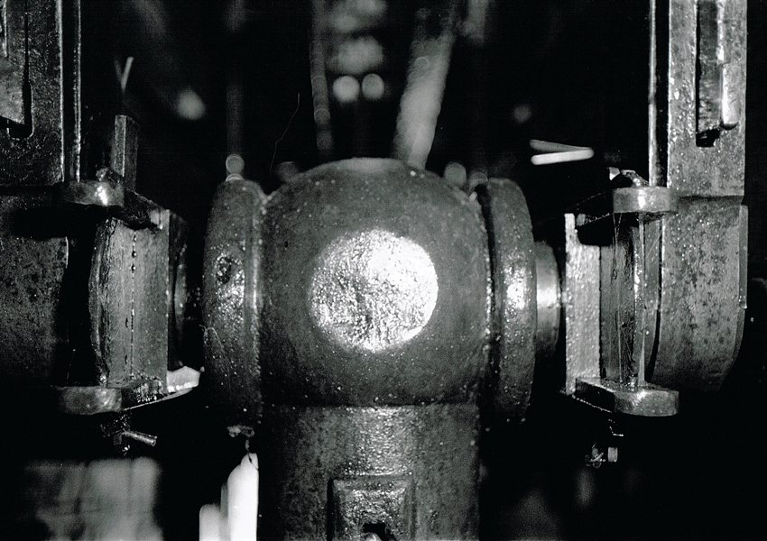
Also on the above photo are the two eccentrics, one for each direction of travel of the engine. These control the opening and shutting of the inlet and exhaust valves of the engine. They were installed after the engine ran away, with the consequent burst of the flywheel, parts of which were found in the zawn after going through the roof of the engine house (frightening). Eccentrics were thought to be much better at controlling the engine than being worked off the plug rod as before.
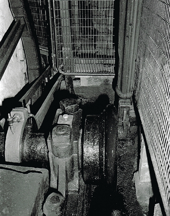
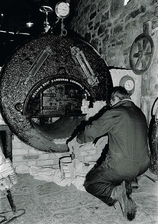
The engine remained here greased up and preserved for many years. During the 1980’s cosmetic restoration was commenced with permission given by Geevor who were operating the site at the time.
Members of the Trevithick Society began work, this progressed into a team of dedicated enthusiasts who became known as “The Greasy Gang”. Led by Milton Thomas this group of amazing people finally brought the engine to steam during 1993. What a brilliant project to be involved in, they derserve so much thanks and respect.
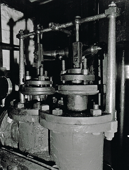
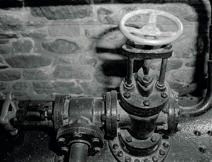
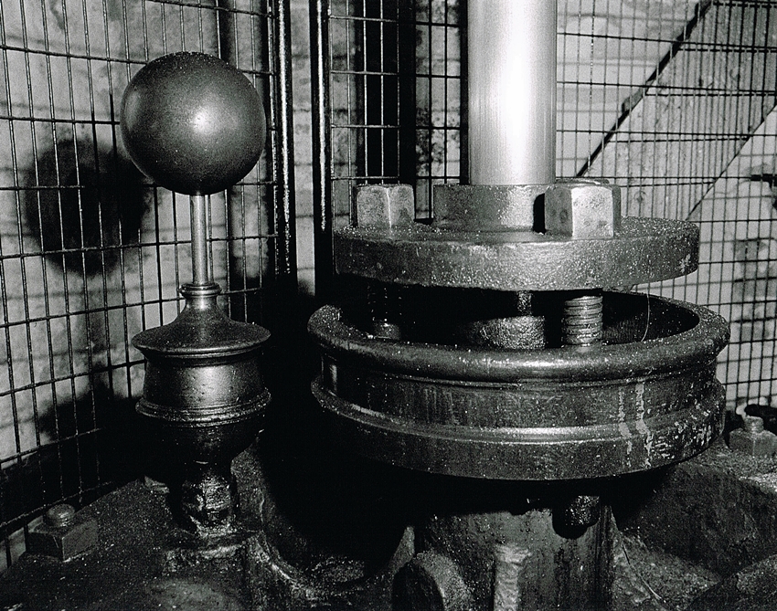
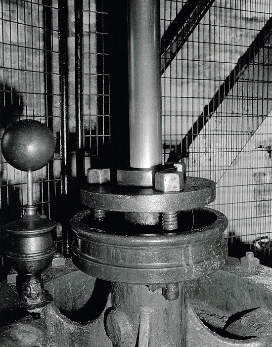
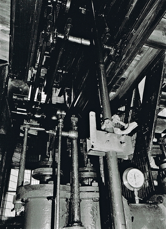
The valves shown, (two) of the set of 4 on this engine are used to control the inlet and outlet of steam to the engine and are the inlet and exhaust valves. They work in pairs at opposite ends of the cylinder, that is when the inlet valve at the top of the cylinder is open admitting steam above the piston. The exhaust valve at the bottom of the cylinder is open to the condenser causing the piston to travel downwards in the cylinder.
When the piston reachs the bottom of its stroke, these valves are closed and the bottom inlet and top exhaust valve are opened causing the piston to rise in the cylinder. Hence the engine is double acting, having a power stroke in both directions. These valves are controlled by the eccentrics on the crankshaft. The valves can be operated by either eccentric, allowing the direction of rotation of the flywheel and drums to be reversed.
This allowed winding in both directions, the two rope drum allowing one skip to be raised and the other lowered in the shaft, the skip be lowered became the one raised by virtue of which eccentric was operating the valves.
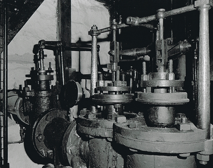
The throttle valve is to the left of the inlet valve, with the exhaust valve nearest camera. The throttle valve is controlled by a long lever operated by the engine driver, this is used to control the speed of the engine. It is used to start and stop the engine.
Linching the crank to the right postion using this valve is one of the skills of driving this engine and allows the piston to be stopped in the best position for starting (mid cylinder) the crank horizontal, allowing easy starting in either direction. Top dead or bottom centre on this engine are a no no,as the engine does not like to start from this position and can mean barring off this position.
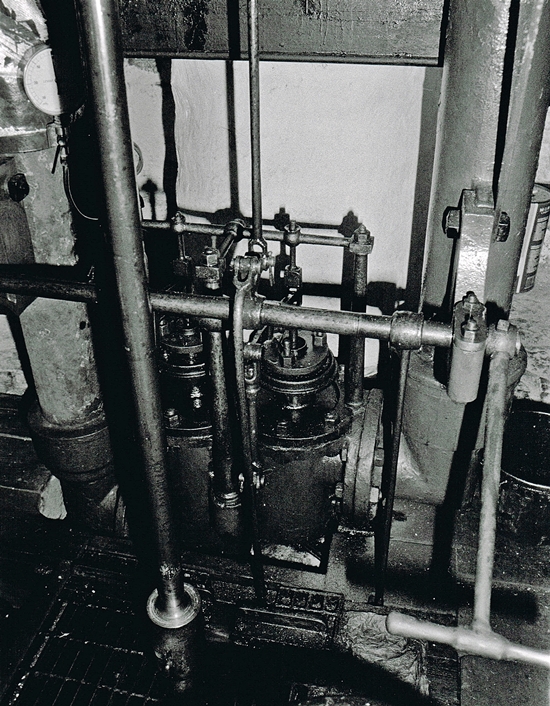
The image above is the bottom valve chest, with the inlet valve on the right and the exhaust on the left. Link pipes join both sets of valves, with the inlet link pipe connected to the throttle valve and the exhaust link pipe connected to the condenser.
Only one valve at each end of the cylinder can be opened at once. Therefore if the top inlet is open to steam the bottom exhaust is open the separate condenser and vice versa.
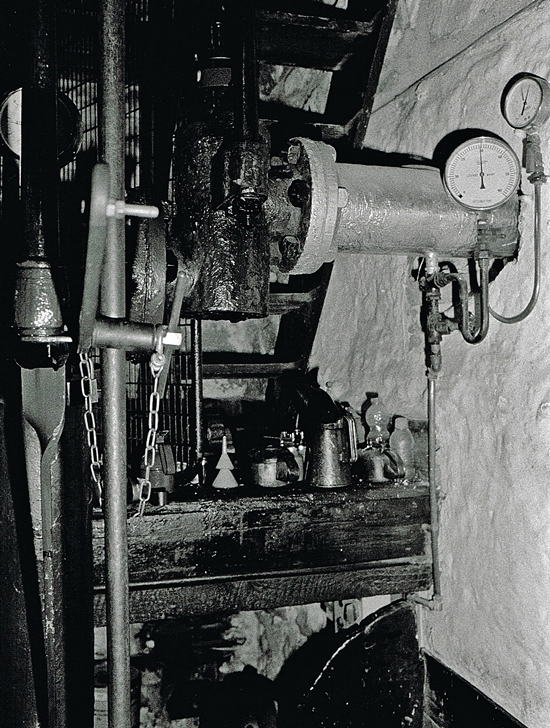
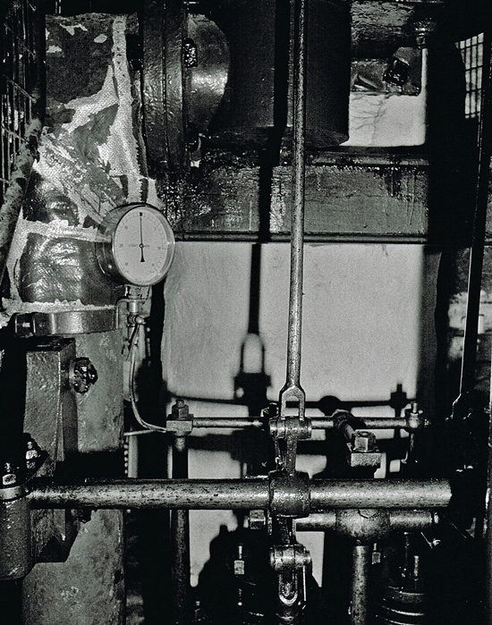
I was quite lucky that the site was closed for maintenance, it meant I could have a good look around also some of the protectve screens were opened for me.
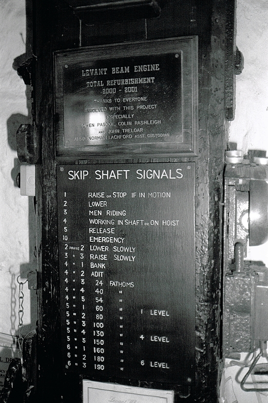
The site is now managed by the National Trust.
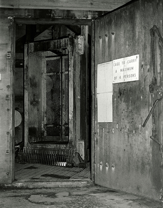
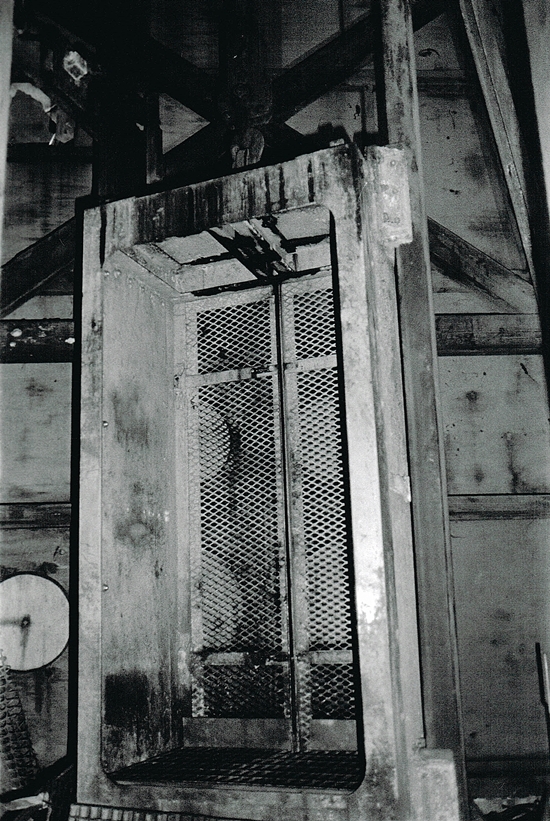
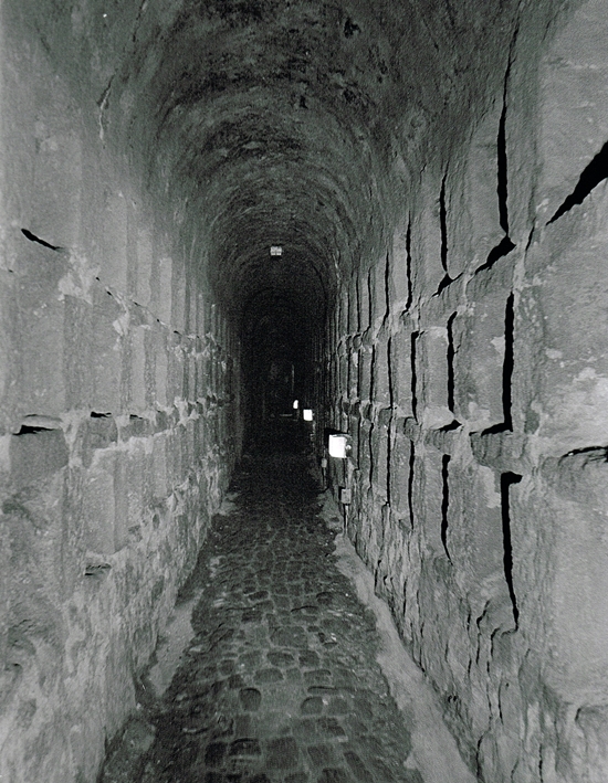
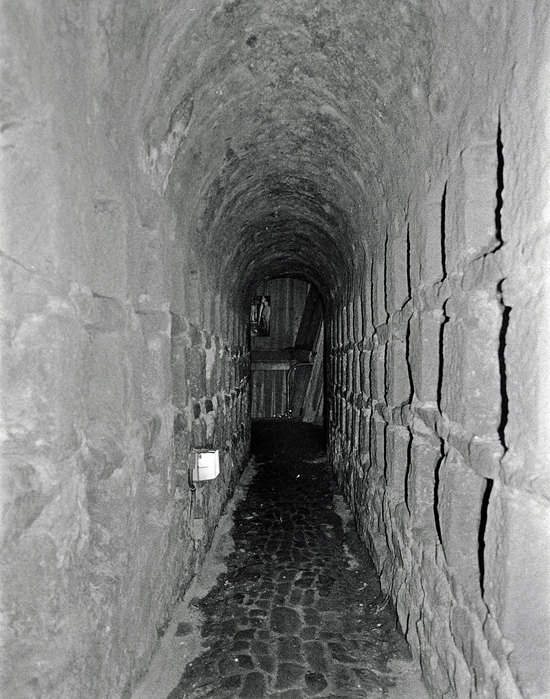
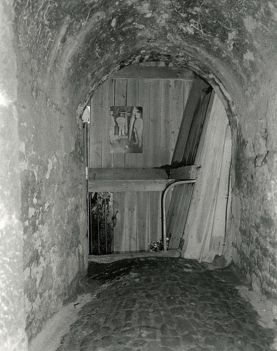
The following set of images were taken in the tunnel that leads from the Dry to the Man Engine Shaft. This is the site of the dreadful accident in October 1919 when 31 miners tragically lost there lives.
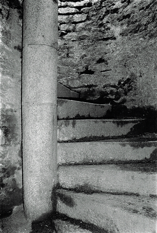
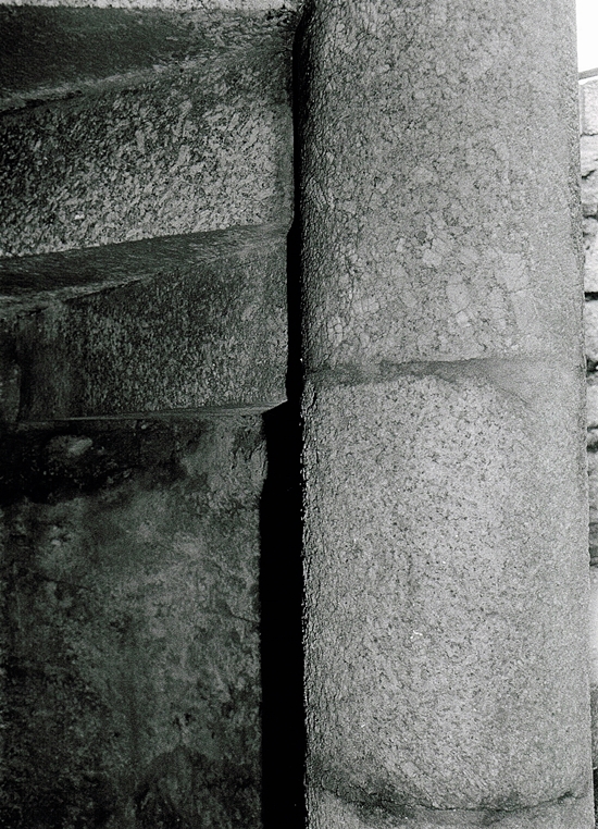
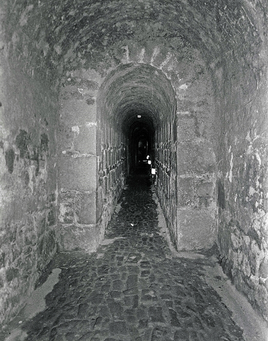
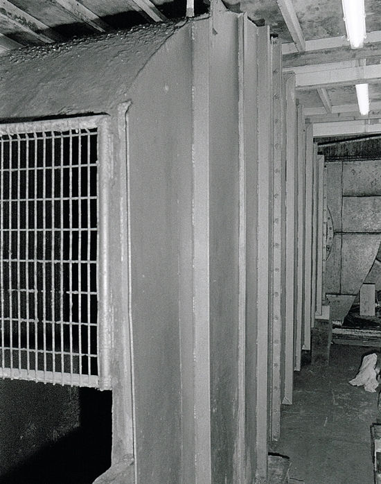
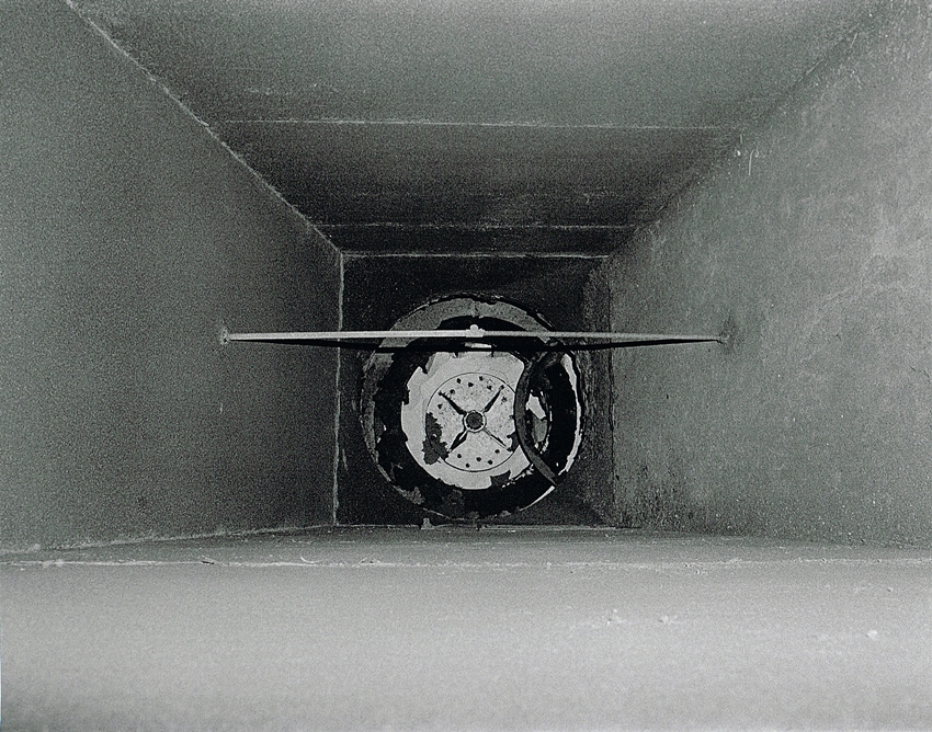
Returning to the area around Skip Shaft these next few images were taken in the fan house. Whilst Geevor Mine was operational is was important to keep the workings clear of bad air.
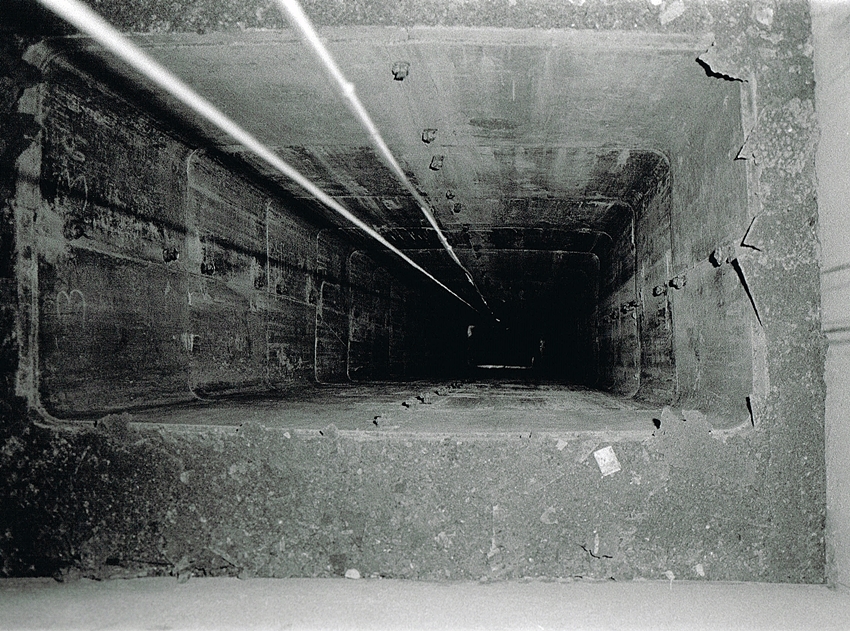
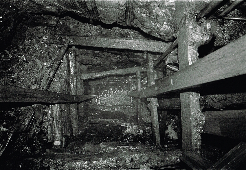
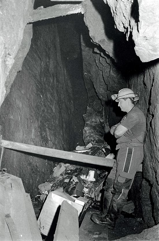
This is the entrance to the top of Skip Shaft. I had the amazing opportunity to climb down the ladders in 2016. Even then the upper section of the shaft had deteriorated badly with much of the timber work start to decay and drop down the shaft.
